Designing and 3D printing a custom wrench
(This article is mostly for my own benefit, documenting how I did this so that I can easily replicate the process in the future...)
Yes, we have a 3D printer on board Away To Me (a Prusa Mini+). It's gotten quite a lot of use recently.
Sometimes you need a part that isn't commercially available, or one that isn't readily available where you happen to be and you need it right now, or one that doesn't cost hundreds of dollars (yes, boat stuff tends to be exorbitantly expensive).
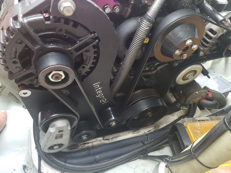
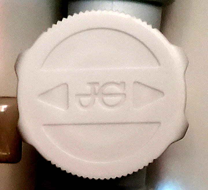
In this case, we have these pex valves that control which water tank the pump pulls water from.
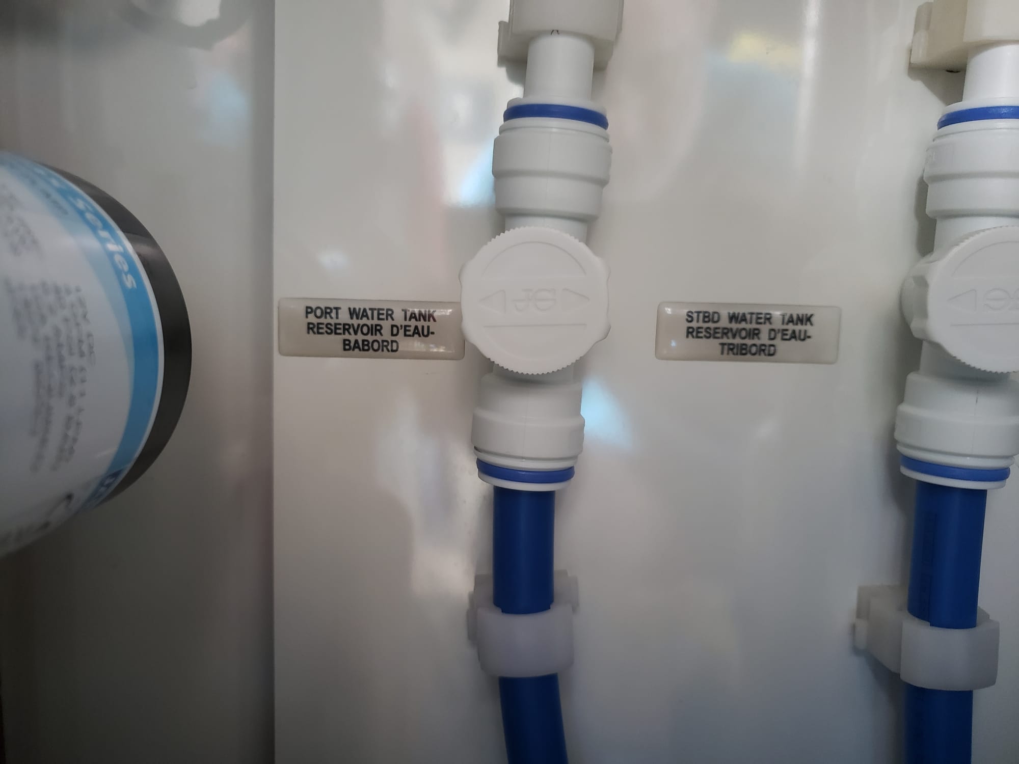
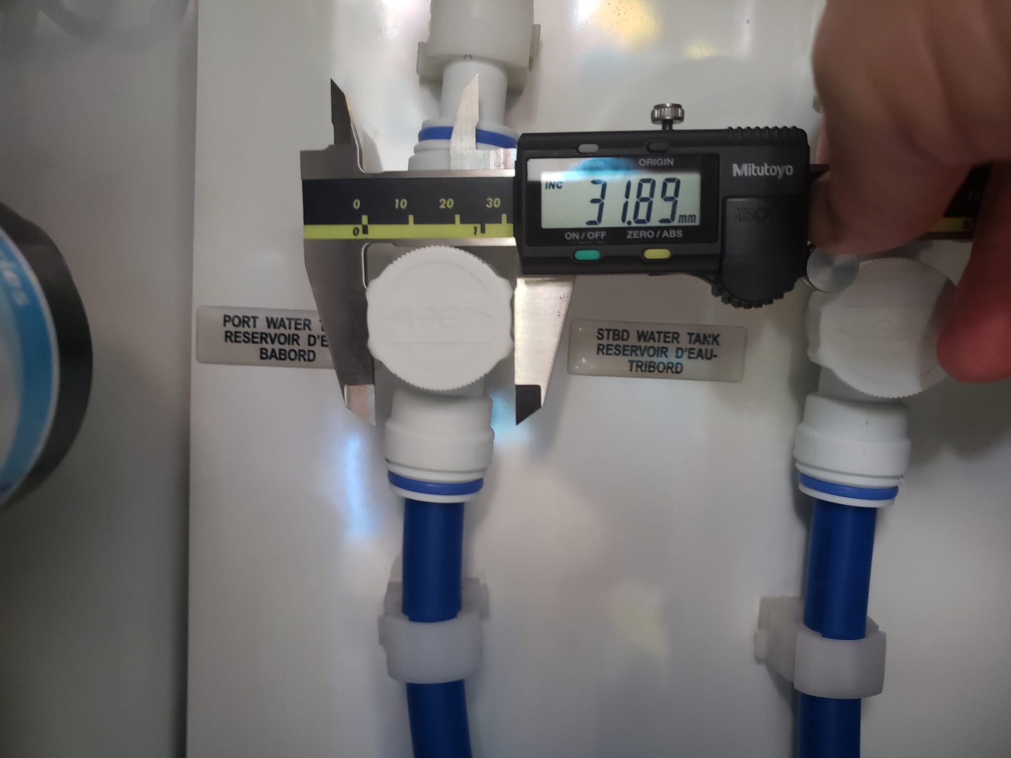
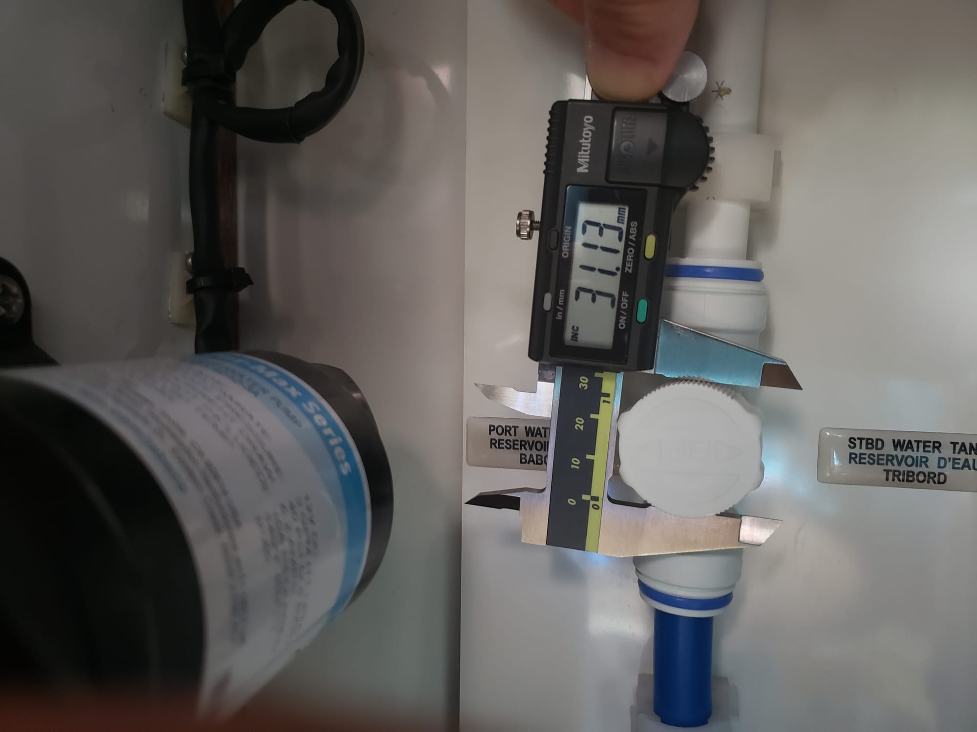
They are small, only 34mm across (1.3 inches), tight and hard to turn, and provide almost no grip. Plus, inevitably, you end up needing to swap tanks while you are doing dishes or washing your hands, so they are wet and soapy, meaning you have even less grip.
This small valve is a funny shape, and the features that could be used as mating surfaces for a wrench have very tight tolerances. I started off trying to measure things with calipers and drawing it in CAD software, but this proved futile. There was no way I was going to be able to reproduce this with any level of accuracy, and it would take many many hours just to try it.
After doing some research, I found a useful gimmick for creating a 3D model from a picture. There are a few important steps:
- Take a high quality image face-on, with high contrast.
- Upload the image to Convertio, telling it to convert the file to the .dxf CAD format.
- Download the .dxf file it produces.
- Import the .dxf file into your CAD software. You will likely have to fix some issues (removing extraneous lines, etc).
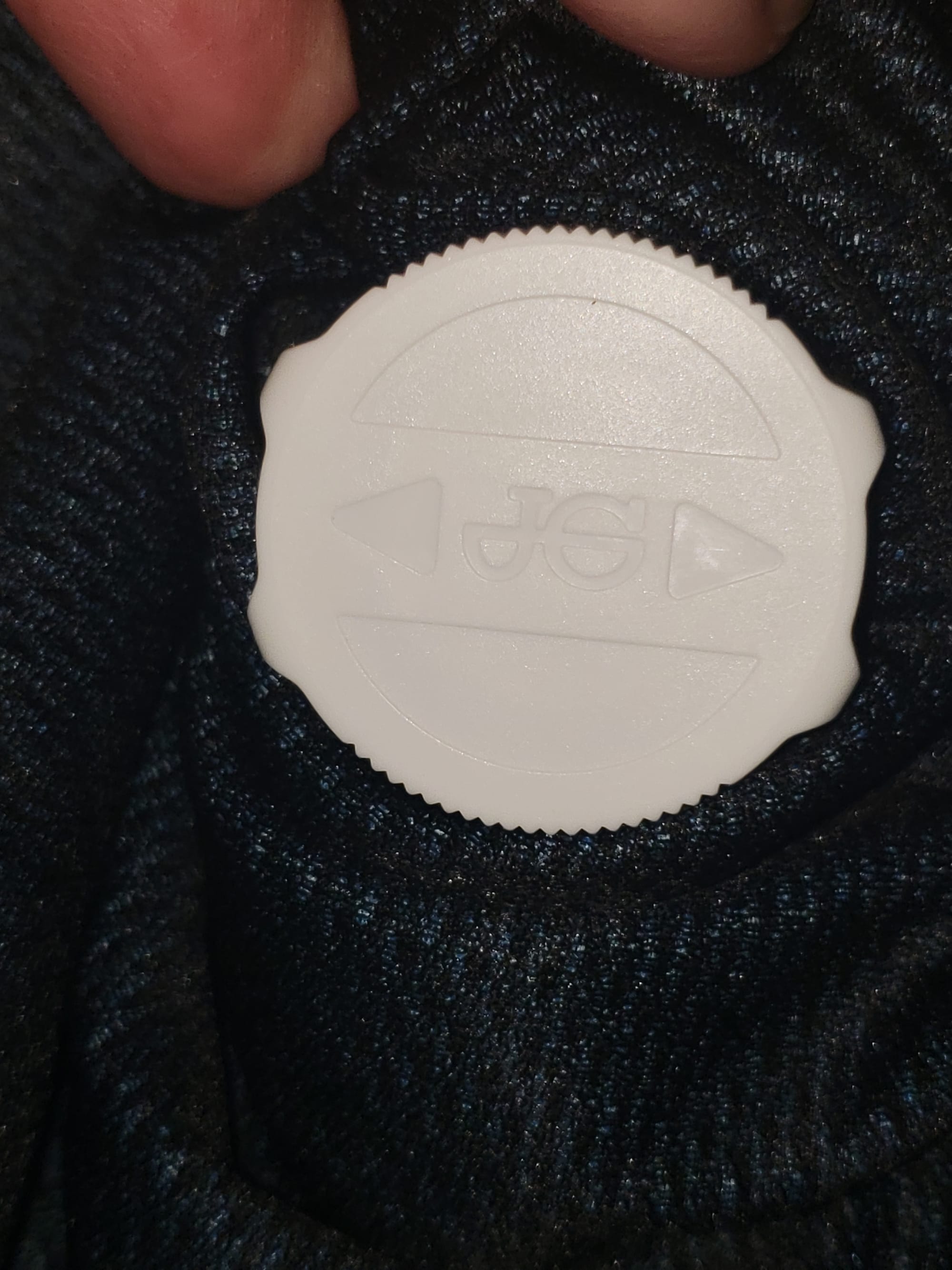
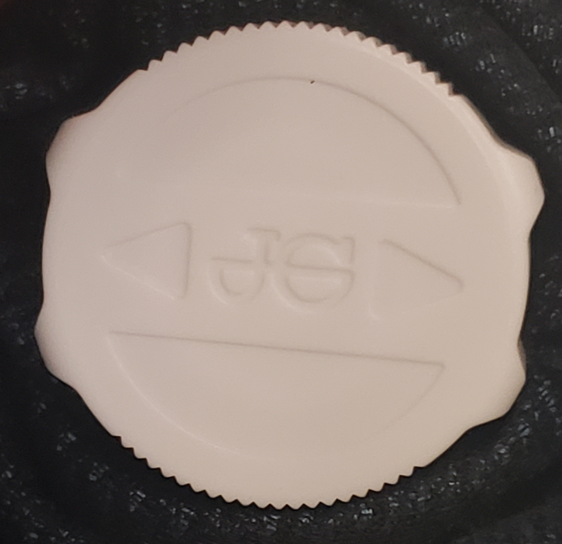
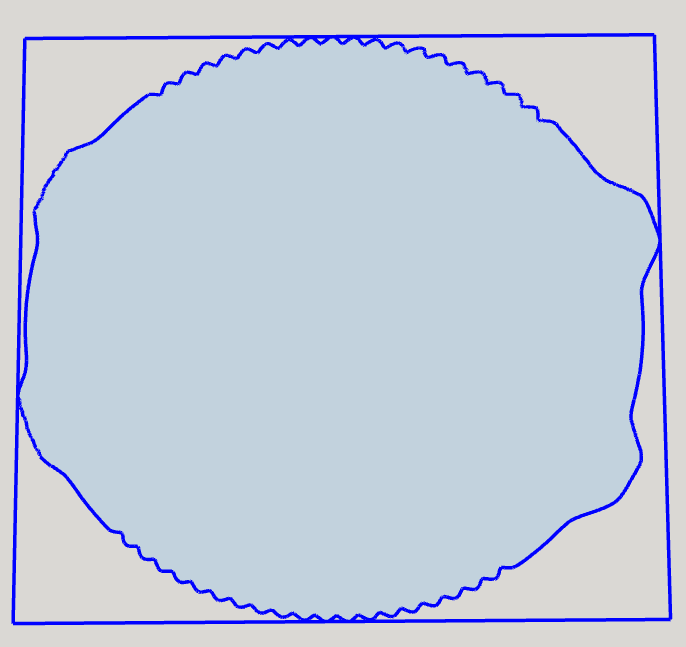
In order to get the high contrast image, I wrapped a piece of black cloth around it, then I edited the picture to remove as much irrelevant stuff as possible. The result was fairly good, having just a few issues to fix.
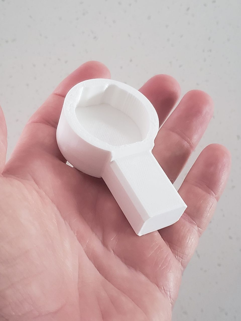
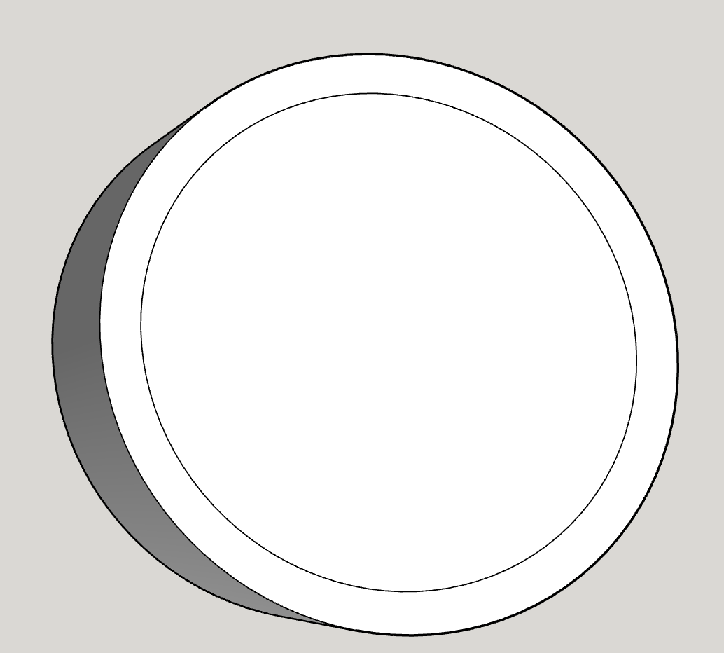
After that, it's just a matter of creating the 3D geometry for the wrench body, which is a cylinder that is sufficiently larger than the valve to provide lots of layers of printed plastic for strength. On that, I placed a circle that I wanted to scale the converted .dxf file to. This is about 0.3mm larger than the actual valve, so that there is a little clearance, but not too much. I want the wrench to slide on easily, but not to be too wobbly.
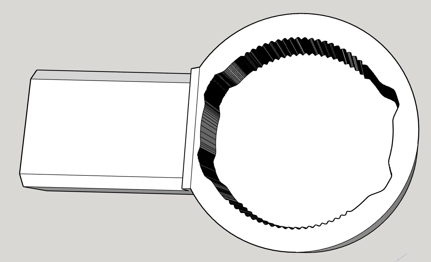
Once I got the .dxf object placed and scaled to match the inner circle, I just used the object to extrude into the cylinder to make the socket. Then it was a simple matter of adding the handle to the side so that we can apply torque to the wrench.
After that, I just had to follow the usual work flow for 3D printing: export the object to a .stl file, import it into the slicer software, then get it to slice the model and export the gcode file.
Easy peasy!